|
|
Problem description
The large area imaging detector is composed of a matrix of sensitive detector
tiles. Each tile consists of a single Timepix device with an edgeless silicon sensor. These tiles
are placed side by side without any gaps. Thus the whole area of the device is
fully sensitive.
|
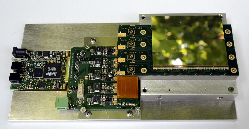 |
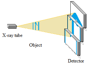
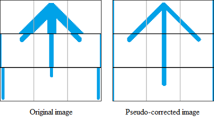
Image taken by WidePix should be "zoomed and deformed" as demonstrated in the image below.
Deformation mainly depends on the X-ray tube and detector distance, but it can also be affected by the distance between the rows of chips.
Some photons throw out among the border of the bottom rows and some photons are counted twice on the border between top rows.
So Paralaxa plugin can transform an image from partial planes into a plane across the whole image.
|
 |
|
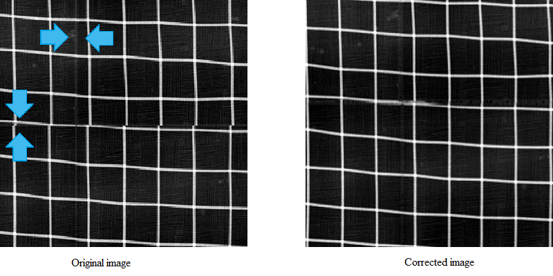
The hugest deformation is seemed on images from WidePix 10x10 camera. Measured object is a wire mesh.
In the below images you can see a part of crossing chip. The image taken from the detector is on the left side and on the right side is the corrected image.
In the original image you can see three problems.
First, the brightness of the vertical border of chips as some photons hit two pixels.
Second, the smaller size of horizontal border of chips, so squares seem like rectangles.
Third, the wires are not continuously connected.
Due to bigger pixels on the chip borders, the wire is a little bit smoothly along the chip edges after the correction.
|
 |
Operating Paralaxa plugin for
Pixelman
The Paralaxa plugin performs image transformation as described above. The installation and applies steps are as follows:
|
|
0) Plugins "paralaxa.dll" and "JParalaxa.jar" library must be added to Pixelman.
|
|
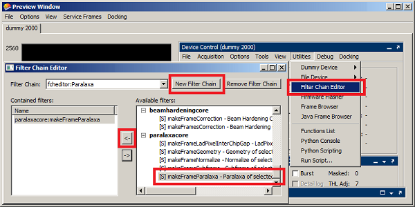 1) Paralaxa should be added to existing filter chain or created as a separated filter.
Filter Chain Editor is accessible from "Main Menu -> Utilities -> Filter Chain Editor".
A new empty chain is created by click on the button "New Filter Chain" and after entering the name (for example "Paralaxa").
Then available filter can be assigned to the chain. The library "paralaxa.dll" contains filter with prefix "paralaxacore".
You can follow partial steps of Paralaxa algorithm step by step: "makeFrameLadPixelInterChipGap", "makeFrameGeometry", "makeFrameNormalize" and "makeFrameSubFrames".
Alternatively, you can use the there method "makeFrameParalaxa" which contains all steps together (this option is the fastest because of over head by calling functions). Selected function method is assigned to chain by pressing the button "<-".
|
|
2) Paralaxa settings must be set before the filter application. The dialog with parameters can be accesed from "Main Menu -> Tools -> Paralaxa". If "Paralaxa" titile is missing, it means that "JParalaxa.jar" library is not installed correctly.
|
|
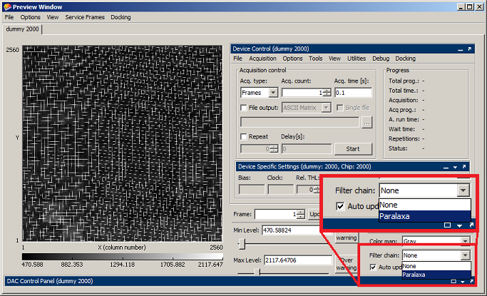 3) So after creating filter chain called "Paralaxa" and setting the filter options, the chain is ready to use.
Application on current data is performed by selected "Paralaxa" in combobox "Filter Chain".
If there is an option "use Paralaxa" from another tool for Pixelman, please use it before the "Paralaxa".
It is recommended to use the "Paralaxa" tool as the last filter in the chain.
|
Plugin parameters
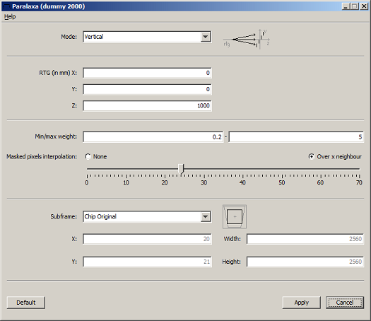
Plugin parameters can be changed in the "Paralaxa" dialog, which is accessible from main menu "Tools -> Paralaxa".
User should change a position of X-ray tube and WidePix detector according to current measurement.
You can restore default value of parameters by pressing the "Default" button.
Chip and detector geometry is stored in the file "[Pixelman]\configs\paralaxa_[device_name].ini", that is generated by a device vender and it can not be modified by user.
|
 |
| Parameter
|
Description
|
Mode
RTG x,y,z
|
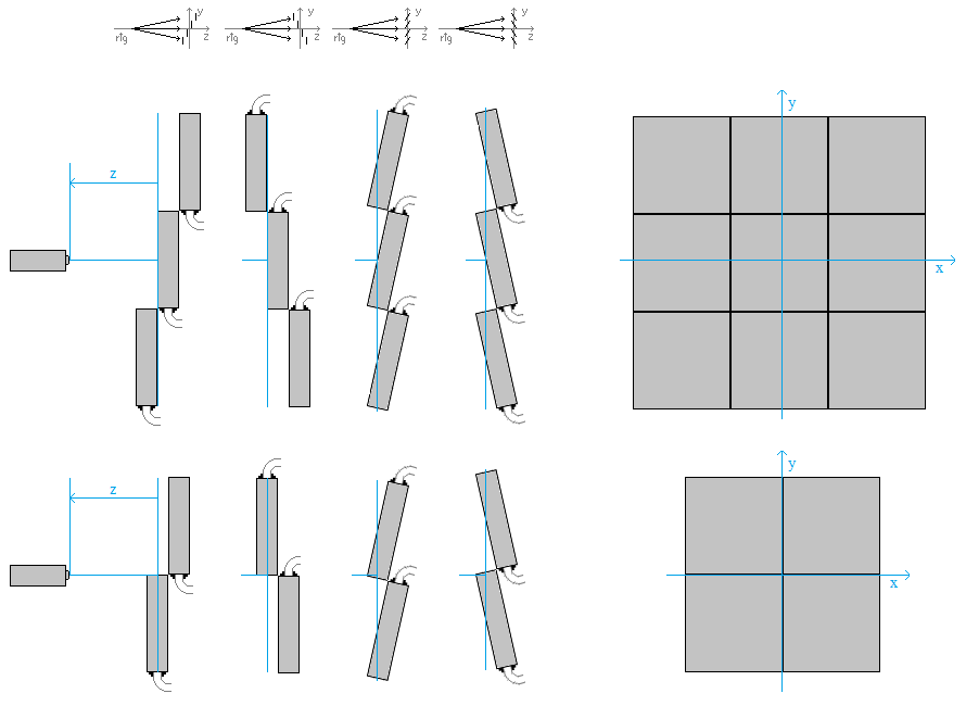
These parameters describe a position between the x-ray tube and detector, their values depend on odd/event number of chips in row/column.
X and Y means the x-ray tube offset from the centre of the detector scanning area (0 value determines, that the x-ray tube and detector is in a plain).
The distance of the x-ray tube and detector is marked as Z coordinate. For an odd number, "0" is in the middle row and for event number 0 is between two middle rows.
The tilt of chip area is called "Mode". There is two basic positions. Either "Vertical1/Vertical2" for the long distance or "Slant1/Slant2" for the short distance (about 20xm and nearer).
For better undertanding, refer to the above pixtures. The coordinates X,Y and Z are masked by blue color (zero plain).
It is evident that centre of detector depends on the odd/event number of chips.
|
| Min/max weight |
According to the detector geometry and position between the x-ray tube and detector after the stretching image into one (zero) plain, pixels have a different signal strength.
So, the pixel value must be normalized. Too small or to big pixel value will be masked.
|
| Masked pixels interpolation |
The Plugin detects defective pixels (noisy, dead or with incorrect values) and replaces them. Interpolation is using the weighted average of the neighbouring pixels (weighted by distances). The algorithm allows to interpolate large continuous areas (but it is CPU intensive). Option "None" disables this functionality.
|
| Subframe |
The image after Paralaxa correction is bigger (each chip gets 4 pixel more).
For example, the original image taken by WidePix 10x10 has 2560x2560 pixels and the corrected one has 2600x2600 pixels.
The option "None" return the biggest image (2600x2600 pixels).
If "Chip Original" is selected, the returned image will have the same pixel resolution as the original taken image.
The option "Inner" return the biggest inner rectangle after the correction.
User has to fill X, Y, Width and Height for the rectangle if the "Custom" option is selected.
|
|
 |


